Here is a procedure to install the ESP-off button on the Corsa D pre-facelift.
It’s important to note that, as in previous articles, in this case the modification voids the warranty and also for driving you have to do the review. I’m not responsible for any work done to your car. If you try to run the below at your own risk.
Abstract:
- There must have the ESP
- Your model must be pre-facelift.
What you need:
- The switches on the centre console (where the hazard switch is) with the ESP button (below is a photo) or, alternatively, Park Pilot, heated seats …
- If necessary, replace the console (see below).
- If you do not have the necessary wiring between the switch and BCM must be added (see below).
- Programming Tech2 or OP-COM programming.
- Screwdriver, Torx, welder (depends), shrink (depends).
As for the keys there are dozens of variants with or without a heated steering wheel, heated seats, DDS, ESP and Park Pilot. You must choose the right one for you, there are many codes in this regard. You can even buy the keys including the DDS but no heated seats and use one of two for this function, but … not the best, isn’t it?
In addition, the Park Pilot and the ESP button are reciprocally exclusive, or one or the other … the choice is yours … so:
If you already have a Pilot Park (parking aid) you can go directly to programming IF you choose to disable it and convert to the ESP function. Otherwise you can use another button.
Council, if you have the basic version, you can take the code 13276392 for GM: Hazard, closing doors, ESP off, airbag off. (About 70 €)
Instead, for the coverage that can afford the housing codes of the buttons are:
- Piano Black: 13208692 / 2010-on:
- Coal, Anthracite: 13247406 / 2010-on:
- Satin Dark: 13208691 / 2010-on:
- Matt-crhrome: 13208693 / 2010-on: 13295123
And the price is about 60 €.
Procedure:
Here’s how to proceed in
- Remove the top of the console
- Check if we have already designed. If you have go to point 4 otherwise proceed
- Provide links
- Pull the instrument panel
- Route the cables and connect
- Replace all
- Install the new buttons and replace the console
- Program our car
WARNING: turn the ignition off, remove the ignition key to avoiding involuntary.
1. Remove the top of the console
a) With a thin screwdriver to pry along the cutting edge of the network which covers the 7 th speaker. Once raised, if you have air conditioning, sure to disconnect the sensor.
b) Unscrew the screw that you will find in part to the glass.
b.bis) If you have the GID / CID remove it by undoing the 2 torx screws on either side
b.tris) If you do the TID lever to remove the entire block, the front is anchored by the notches
c) Remove the radio.
d) Remove the metal frame.
e) Leveraging with two screwdrivers (but not too tightly) move the clips that are located in the upper corners of the car. The clips in question are part of the piece of plastic on which are placed the switches.
f) Then pull forward making sure that the buttons are connected to after lifting the top.
2. Ensure the predisposition
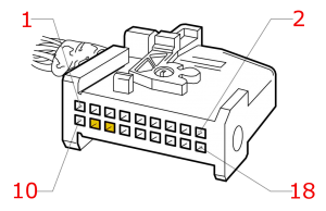
Looking at the block can see a bundle of wires that terminates behind the buttons. To separate the contact plate from the connector just move the lock lever which has a kind of spring. Loosen the closure is possible to remove the connector. Do not pull the strings!
Now that we have in hand to check if the connector pins 11 and 12 are occupied or not.
If the pins in question are occupied go to step 4, if it were free … congratulations you have won the point 3!
3. Create links
If you have arrived at this point means that you do not have the predisposition of the button. To overcome this problem you need to create the connections, then spend a few wires and creating the connector.
Go to a VW dealer to buy the 4 connectors (two wire, the wires are two) VW 000979018EA code. In reality there are attached to the connectors of the wires … I know but if you find another way to get the connectors let me know. Take two pieces of wire and 1 m diameter of 0.35 mm ². I recommend you take two colors that will allow you to recognize them immediately, also take some tie to anchor them and do not let them dangling.
The steps are:
1) Remove the lower part of the dashboard, one which covers from the knees of the driver. It ‘should remove the panel covering the fuse in, then unscrew the torx that hold the cover on the dashboard.
2) DISCONNECT THE BATTERY
3) There will be next (oh yes … you have to have a lot of light) the BCU (Body Control Module). Recognize that because, in addition to fuses, two connectors that come, the central one very long and left a small, almost square. The clips that stop them are blue.
4) Write down the positions (up-down) because you have to disconnect the connectors. Here, now disconnect them 😀
5) Unscrew the Torx screws that allow you to pull the unit towards you. But beware:
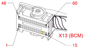
6) Behind there are 2 connectors that must be disconnected and you have to REMEMBER THEIR POSITION and NOT PULL THEM. One of them is the connector X13. This is what interests us and, in my case, is the lower one.
7) Take your wires, make them pass from the center console to the position of the unit and cut with a surplus of 20 cm of freedom. The path is yours, I suggest you get off to the side of the car and go under the steering wheel.
8) Now, armed with soldering iron and heat-shrinkable sleeve, cut the ends of your VW wires 5 cm and solder the ends of these wires. Be careful to get the work done because they do not absolutely have to make contact with other wires or grounded.
9) Without pulling, disconnect the front from the back of connector X13 (mine is gray).
10) The switch must be connected from pin 11 of the button to pin 28 of X13.
11) The confirmation LED should be connected from pin 12 of the button to pin 13 of X13.
12) The pin numbering is according to the following scheme:
13) The connectors must be inserted in here setted in the orientation of the adjacent ones, because only in that way it will fit properly.
Try pulling gently to ensure that they can not move from their home. If they move try to rotate a quarter and retry.
14) Test with a multimeter if the link is correct
15) Reassemble everything in reverse order making sure to attach the connectors to the BCU WELL
4. Install the new buttons
If you had to buy a new panel replaced with your new one, assemble part of the dashboard that can accommodate.
But if you just plain that want to convert an existing button you have to swap the pins 11 and 12 with the ones of the button you want to use.
Then proceed to the install the cover back on the dashboard and do the steps you have done to take it apart.
5. Program the car
Connect the car battery if you disconnected in the above paragraph where I mentioned there (otherwise you are really lucky :D).
Turn on the ignition and the lights on so that you check the back-light illumination of the buttons. If it does not go back to check the connector: it might not be properly connected.
If you have prepared the Tech 2 and the security code of the car follow the steps, or else go from your Opel dealer and ask them for you:
Step One: Body / BCM / variant configuration: Switch ESP / TC OFF: Present
Step Two: Body / IPC / variant configuration: ABS / ESP: ESP & ABS for OPC
Disconnect the Tech 2, turn off the car.
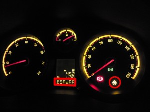
If you followed the steps correctly turn the ignition on, if you press the ESP off ESP you will see the symbol on the dashboard. Congratulations!


Friday March 9th, 2012 at 12:58 AM
It’s the best time to make a few plans for the future and it is time to be happy. I’ve read this publish and if I could I want to recommend you few attention-grabbing things or advice. Maybe you can write subsequent articles referring to this article. I wish to read more things about it!
Wednesday April 18th, 2012 at 01:11 PM
Ok Funny Cat Stuff!
I’ll do it
Wednesday March 28th, 2012 at 02:18 AM
A better magazine theme would make the blog nicer.:)
Wednesday April 18th, 2012 at 01:12 PM
Thanks Belen for your suggestion!
Tuesday April 17th, 2012 at 07:39 AM
Great job for all the info published here!
You’ve done a great job!
For the past 2 months i’m studying all the info related to this car&i’m looking forword to buying one.
From what you’ve said at the begining of the article i understand that on a facelifted model (2012) all of the above mentioned steps do not apply.
Please help me out, the model i,m looking forword buying is a 3door corsa A16LEL, it is kind of dissapointing the fact that it will be imposible to disable the ESP&TC (not by the means of a button on a dash).
The above mentioned model is not a GSI/SRI, here in romania from what i’ve seen the equivalent package (sport) is the equivalent of an sxi in the uk and from what i’ve seen on mobile.de on similar models this engine no longer comes with the ESP button (only on OPCs)
Would it be ok if i select as an option the parking sensors? Would this make the job possible? Also if this would be posible could the parking button be moved where the tyre pressure button normaly is?
Thank you a lot for all the info posted here&i’m deeply sorry for all the above questions 🙂
Best regards,
Wednesday April 18th, 2012 at 01:21 PM
Hi Costin, you’re wellcome!
Thanks for your question: glad to help someone with same “hobby”.
I wrote pre-facelift because I’ve not disassembled any 2012 version nor I have any schema.
The above model is a “Sport” one, the “SXI”. The ESP off button comes with the OPC/VXR and GSI/SRI models (as far I know).
If the BCU has not changed, yes: you can buy the parking sensors. You should then connect the TPMS or seat heater button pins to the “ESP off” equivalent on the BCU.
You follow me? If you’re interested in Corsa than we can see it later when you’ve the car!
Wednesday April 18th, 2012 at 04:43 PM
Thanks a lot for your response, i can barely wait to get my hands on the car. You’ve really raised my hopes regarding this concern of mine.
At the moment i’m trying to get a better price on it from the dealers and also on my present car.
Looking forword mingleing with this car, i’ll post some pics as soon as i get it…unfortunetly it will take a while..from what i’ve heard it takes aprox 3 months to deliver it (if there is none already produced with my desired specs)
Thank you for your time and once again great job with all the info posted here!
Wednesday April 18th, 2012 at 09:18 PM
I’m glad for you!
Please let us know when you’ll get your new car!
About delivering time it depends: 3 months usually is the maximum time (mine tooks 1.5)
Thank you for for joining us!